so i have an 06 250x that wont charge. following the manual i have, it would appear my stator is dead. checked for continuity on the yellow and blue wire with nothing. the bike will run even when the battery is dead when i kick start it, so im not sure how that factors into things.
now being a car guy i know the alternator makes power and the voltage regulator makes sure the system doesnt over charge and charges when it needs it.
so can anyone explain to me what a stator does and a rectifier does?
also, what is the difference between the following, a flywheel?
http://www.crfsonly.com/catalog/product ... ts_id/4695
http://www.crfsonly.com/catalog/product ... ts_id/3643
help me understand bike electrical
-
-
124

- Posts:3704
- Joined:Wed Feb 16, 2005 1:37 pm
Your stator is not dead if the bike runs.
On the X's, the stator has 2 coils that each have a separate function. The picture below is from a 450x but should be the same.
The ignition one provides a "signal pulse" that is eventually stepped up in voltage by the coil to produce spark for the engine.
The alternator provides AC power to the headlight and to the rectifier. The rectifier (the readers digest version) changes AC voltage to DC voltage. It provides DC voltage to the battery and also indirectly to the tailight.
There are many reasons why the battery won't charge or hold a charge. There should be no continuity between the yellow and blue wires coming out of the stator.
EDITED - Removed wiring diagram. 450X diagram posted is NOT representative of the 250X being discussed...Last edited by 124 on Tue Sep 11, 2012 6:03 am, edited 1 time in total.70' Honda CT70 (Trail 70; Gold)
16' KX450
16' KX85
12' YZ125 -
-
-
gal8x

- Posts:638
- Joined:Mon Mar 12, 2007 5:36 pm
You should have some small resistance between blue and yellow and ground. Make sure you VOM is set to Ohms and not continuity. Check with the stator unplugged. Make three tests Y to ground, Bu to ground and Y to Bu. You should get three slightly different readings.
Your service manual it will tell you how to trouble shoot your electrical system, specifically where to test and what to look for (You do have one?). You should also check your voltages at the rectifier. In all my years I have never seen an OEM rectifier go bad. My guess is you have a bad connection or a busted wire.2005 CRF450X (plated)
"Can't never could do anything" -
-
-
gal8x
- Posts:638
- Joined:Mon Mar 12, 2007 5:36 pm
Re: help me understand bike electrical
mobil1syn wrote:
also, what is the difference between the following, a flywheel?
http://www.crfsonly.com/catalog/product ... ts_id/4695
http://www.crfsonly.com/catalog/product ... ts_id/3643
Yes.2005 CRF450X (plated)
"Can't never could do anything" -
-
-
crfsonly

- Owner
- Posts:9651
- Joined:Thu Apr 01, 2004 3:45 pm
Re: help me understand bike electrical
mobil1syn wrote:also, what is the difference between the following, a flywheel?
http://www.crfsonly.com/catalog/product ... ts_id/4695
http://www.crfsonly.com/catalog/product ... ts_id/3643
the less expensive kit is a replacement stator and rectifier only. the more expensive kit includes the stator, rectifier and flywheel.OEM Parts for Honda - Yamaha - Suzuki - Kawasaki: http://yeltrik.com
_________________
CRF Parts and Accessories: http://crfsonly.com -
-
-
mobil1syn
- Posts:22
- Joined:Tue Mar 08, 2011 1:28 pm
124 wrote:The alternator provides AC power to the headlight and to the rectifier. The rectifier (the readers digest version) changes AC voltage to DC voltage. It provides DC voltage to the battery and also indirectly to the tailight.
ok this is interesting. the taillight has always worked and the headlight leads (no headlight, previous owner put a R plate on it) doesnt appear to have power to it.
looks like i need to start tracing more wires - ugh. i just want to ride
update - started bike with no battery. tail light is dim at idle and ets bright when reving the bike. with a volt meter i get ~2 volts at idle at the head light prong and ~12 while reving.
so it would appear the electrical system is sufficent to operate the bike. is there any fuses in the system other than the 15amp main fuse?
update2 - entire wiring harness checks out. back to the alterator/rectifier. -
-
-
gal8x
- Posts:638
- Joined:Mon Mar 12, 2007 5:36 pm
I don’t think this is normal. I pull from this line to run my sub plastic/frame LEDs as well as the stock fender light. My voltage is constant regardless of RPMs and yours should be too. You may have an issue affecting your ignition control module.mobil1syn wrote: update - started bike with no battery. tail light is dim at idle and gets bright when revving the bike. .
Normalmobil1syn wrote: with a volt meter i get ~2 volts at idle at the head light prong and ~12 while reving.
Nomobil1syn wrote: so it would appear the electrical system is sufficent to operate the bike. is there any fuses in the system other than the 15amp main fuse? .
Your rectifyer
The Red wire with White stripe is the rectifier DC output 12-13.5 Volts
Yellow and Blue are AC in, I don’t know what they should be and I doubt you have the right probe to check but if you set your meter to AC volts and check from ground you should see something on both wires, and something indicates the stator output is fine.
Green is ground (for safty I would ground to frame or battery).2005 CRF450X (plated)
"Can't never could do anything" -
-
-
124
- Posts:3704
- Joined:Wed Feb 16, 2005 1:37 pm
-
-
-
gal8x
- Posts:638
- Joined:Mon Mar 12, 2007 5:36 pm
Yes124 wrote: Please explain further.
yellow goes to rectifier.
No not to ICM to rectifier, and not from separate coils but from the same coil only not all of the same coil… the Blue wire is a ‘centre tap’ it pulls from part of the coil. The diagram may not be a true representation of real-world application.124 wrote: Blue goes to ICM. From separate coils...
The stator has three coils…
1. the ignition pulse generator.
2. the charging coil. Yellow feeding the rectifier & Blue feeding both the rectifier and the headlight . This coil is also grounded.
3. the Excitger coil White and Blue w/White stripe feeds the ICM.
I don’t know if I understand this question but I think this is what you are asking… this is what the inside of the rectifier looks like & why it needs two AC inputs.124 wrote: Why would these be continuous?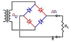
Many motorcycles use a three phase rectifier. I don’t see that here because 250/450s don’t have a third wire coming from the stator.2005 CRF450X (plated)
"Can't never could do anything" -
-
-
mobil1syn
- Posts:22
- Joined:Tue Mar 08, 2011 1:28 pm
-
-
-
Back2-2
- Posts:1148
- Joined:Tue Jan 04, 2011 3:31 pm
Just to throw this out there - Are you sure you just do not have a bad battery that is pulling the electrical system down ?Neil
Black Hills of SD
Life without Motorcycles would just be boring, really boring
Honda 450X. Yamaha Tracer GT900. HD Fat Boy. Triumph Bonneville. Yamaha Majesty 400. Yamaha Grizzly. Yamaha Wolverine. Yamaha TW200 -
-
-
mobil1syn
- Posts:22
- Joined:Tue Mar 08, 2011 1:28 pm
bike has been not charging for a long time. replaced the battery when it first started happening. generally i just toss it on the charger before heading out. kick when i can to save the battery. hasnt been a real problem since i usually do day rides or non-technical (read minimal stalling) last time out i went out it was technical and i am out of shape. the weekend kicked my rear and wrecked my bike. battery was almost dead after day one, and dead on day two.
fatigue led to making mistakes and ultimately to a fall that destroyed my radiator. that was the only thing that saved me physically because i had to stop and let the bike cool constantly, and thus letting myself recover.
since i was replacing a radiator (or two other one is looking haggard) and installing some radiator braces im taking the time to fix the charging issue while im at it.


-
-
-
gal8x
- Posts:638
- Joined:Mon Mar 12, 2007 5:36 pm
-
-
-
124
- Posts:3704
- Joined:Wed Feb 16, 2005 1:37 pm
gal8x wrote:
Yes124 wrote: Please explain further.
yellow goes to rectifier.
No not to ICM to rectifier, and not from separate coils but from the same coil only not all of the same coil… the Blue wire is a ‘centre tap’ it pulls from part of the coil. The diagram may not be a true representation of real-world application.124 wrote: Blue goes to ICM. From separate coils...
The stator has three coils…
1. the ignition pulse generator.
2. the charging coil. Yellow feeding the rectifier & Blue feeding both the rectifier and the headlight . This coil is also grounded.
3. the Excitger coil White and Blue w/White stripe feeds the ICM.
I don’t know if I understand this question but I think this is what you are asking… this is what the inside of the rectifier looks like & why it needs two AC inputs.124 wrote: Why would these be continuous?
Many motorcycles use a three phase rectifier. I don’t see that here because 250/450s don’t have a third wire coming from the stator.
It appears that the 450X wiring diagram I posted is not at all representative of the 250X. My apologies to all for assuming it was. I will delete...
gal - I'm an electrical engineer. I am very familiar with the components but the wiring diagram is what I was using as a source (apparently incorrectly). Thanks for the explaination. The "R" guy signing out of this one...! 70' Honda CT70 (Trail 70; Gold)
16' KX450
16' KX85
12' YZ125 -
-
-
124
- Posts:3704
- Joined:Wed Feb 16, 2005 1:37 pm
mobil1 - This is erking me a bit. The claim here is that the 450X diagram I posted does not represent your machine.
Do me a favor to close the loop please.
How many wires do you have coming from the left engine cover (stator). What colors?
One more thing please. The blue wire coming from the stator. Find the other end by checking continuity. The diagram says it should go to the ICM. Gal claims it goes to the rectifier. Where does it go?70' Honda CT70 (Trail 70; Gold)
16' KX450
16' KX85
12' YZ125 -


Who is online
Users browsing this forum: No registered users and 2 guests
Copyright 2016-2017 © CRF's Only Forums.AllRightsReserved.